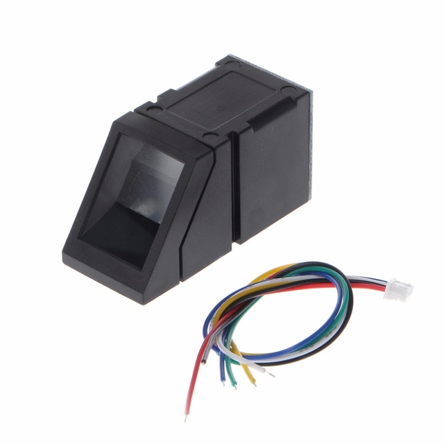
The Output Pins:
- RED -> VCC
- BLACK -> GND
- YELLOW -> RXD
- GREEN -> TXD
Secure your project with biometrics – this all-in-one optical fingerprint sensor will make adding fingerprint detection and verification super simple. These modules are typically used in safes – there’s a high powered DSP chip that does the image rendering, calculation, feature-finding and searching. Connect to any microcontroller or system with TTL serial, and send packets of data to take photos, detect prints, hash and search. You can also enroll new fingers directly – up to 162 finger prints can be stored in the onboard FLASH memory. There’s a red LED in the lens that lights up during a photo so you know its working.
There are basically two requirements for using the optical fingerprint sensor. First is you’ll need to enroll fingerprints – that means assigning ID #’s to each print so you can query them later. Once you’ve enrolled all your prints, you can easily ‘search’ the sensor, asking it to identify which ID (if any) is currently being photographed.
You can enroll using the windows software (easiest and neat because it shows you the photograph of the print) or with the Arduino sketch (good for when you don’t have a windows machine handy or for on-the-road enrolling) 
Enrolling new users with Windows:
The easiest way to enroll a new fingerprint is to use the Windows software. The interface/test software is unfortunately windows-only but you only need to use it once to enroll, to get the fingerprint you want stored in the module.
First up, you’ll want to connect the sensor to the computer via a USB-serial converter. The easiest way to do this is to connect it directly to the USB/Serial converter in the Arduino. To do this, you’ll need to upload a ‘blank sketch’ this one works well:
- this sketch will allow you to bypass the Atmega chip and connect the fingerprint sensor directly to the USB/Serial chip converter.
- Red connects to +5V
- Black connects to Ground
- Yellow goes to Digital 0
- Green goes to Digital 1
Wire up the sensor as described in the sketch comments after uploading the sketch. Since the sensor wires are so thin and short, we stripped the wire a bit and melted some solder on so it made better contact but you may want to solder the wires to header or similar if you’re not getting good conteact. When you plug in the power, you should see the red LED blink to indicate the sensor is working.


There are no reviews yet.