-
×
 PC817 Photocoupler
1 × EGP3.00
PC817 Photocoupler
1 × EGP3.00
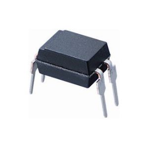 PC817 Photocoupler
 Subtotal: EGP3.00


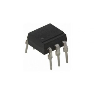
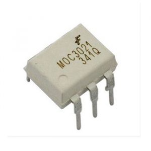
he MOC3041 is a Zero-Crossing TRIAC driven Optocoupler. Meaning it has a Infra-red Light Emitting Diode (LED) inside it coupled with a TRIAC. When the LED is triggered the TRIAC is also turned on.

| Pin Number | Pin Name | Description |
| 1 | Anode (A) | Anode pin of the IR LED. Connected to logic input |
| 2 | Cathode (C) | Cathode pin of the IR LED |
| 3 | NC | No Connection – Cannot be used |
| 4 | Triac Main Terminal 1 | One end of the Triac which is present inside the IC |
| 5 | NC | No Connection – Cannot be used |
| 6 | Triac Main Terminal 2 | Other end of the Triac which is present inside the IC |
| Attribute | Value |
| Number of Outputs | 1 |
| Isolation Voltage(rms) | 4170V |
| Forward Current | 60mA |
| Peak Repetitive Off?State Voltage(Vdrm) | 400V |
| Static dv/dt | 2000V/us |
| Forward Voltage | 1.25V |
| Zero Crossing Circuit | Internal oscillator included |
| SCR Type | Two-way thyristor |
| Operating Temperature | -40℃~+85℃ |
An opto-isolator like MOC3041 is normally used to control another external switching device like a TRIAC, MOSFET or SCR which in turn will control an AC or DC load. The TRIAC present inside the MOC3041 can provide upto 1A peak current which is high enough to trigger an external switch. The TRIAC by itself should not be used to switch loads without an external switch.
Since the MOC3041 has built-in Zero crossing detector it is mostly used in switching AC loads. A Zero cross detector will monitor for the 0V in output sine wave and turn on the internal TRIAC only during 0V. This way the LOAD will not be subjected to peak voltage when switching.
MOC3041 is commonly used in AC motor speed control, Light dimmers or other home automation application where AC load is involed. A typical application circuit diagram to control an ACload using a Microcontroller is shown below

The internal IR LED is connected between pin 1 and pin 2. The voltage source Vcc should be able to provide 15mA through resistor Rin to the Anode pin of the LED. The NAND gate connects the Cathode pin of the LED to ground based on a PWM signal from the microcontroller. So one input pin of NAND gate will be connected to ground while the other is connected to the PWM signal.
Based on the PWM signal the LED will be turned on at particular interval for which the internal TRIAC will also be turned on. When the internal TRIAC is turned on it switches the external TRIAC which in turn controls the AC load. The 39 ohms Resistor and the 0.01uF capacitors forma an optional Snubber circuit. Thus based on the duty cycle of the PWM the output voltage will also vary which enables us the control the speed of intensity of the load.

There are no reviews yet.